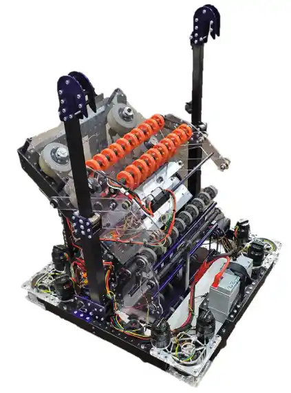
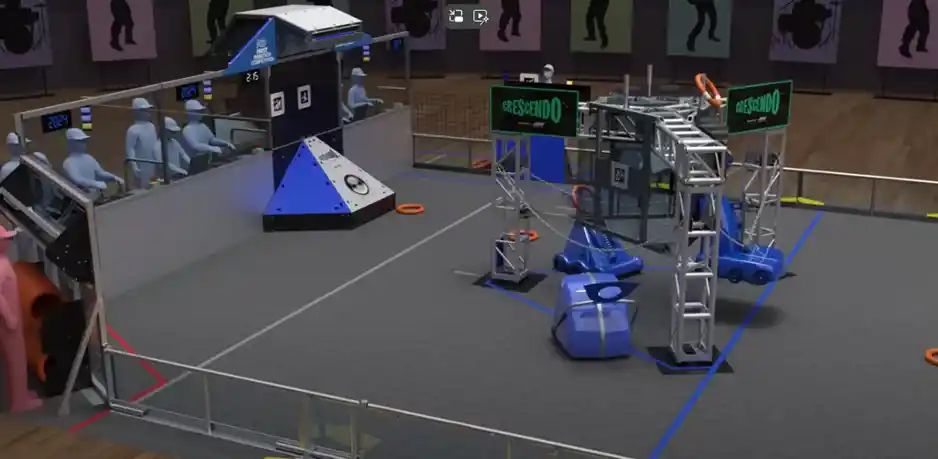
The robotics team continued with building Bruin, the 2024 competition robot, from January up through the first FRC regional competition at Pittsburgh, PA, on February 28th to March 2nd.
Bruin is required to perform three main tasks during a competition match to score points. The robot has to shoot a ring into a “Speaker”, deliver a ring to an “Amp”, and climb onto a “Stage”. Here is a video developed by FRC that shows how the match unfolds and the robots score points during a match.
Once we had the initial design of Bruin in CAD we started to manufacture parts and perform initial assembly. We meet in the Vestal High School shop which consists of two large rooms. One room has tools and tables and an adjoining large classroom to do assembly and testing.
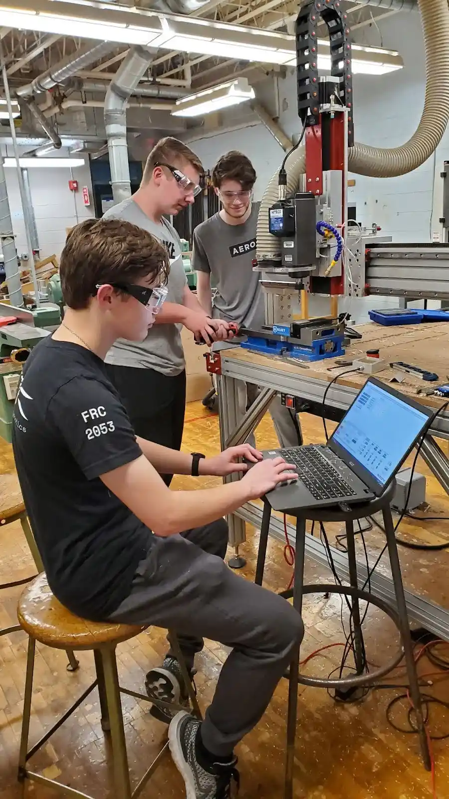
The table router is a key piece of equipment that is used to create wood, plastic, and metal components. The table router is critical in cutting parts accurately in the volume needed. The parts are designed in CAD and transferred to the table router computer which then cuts the parts out of the required material.
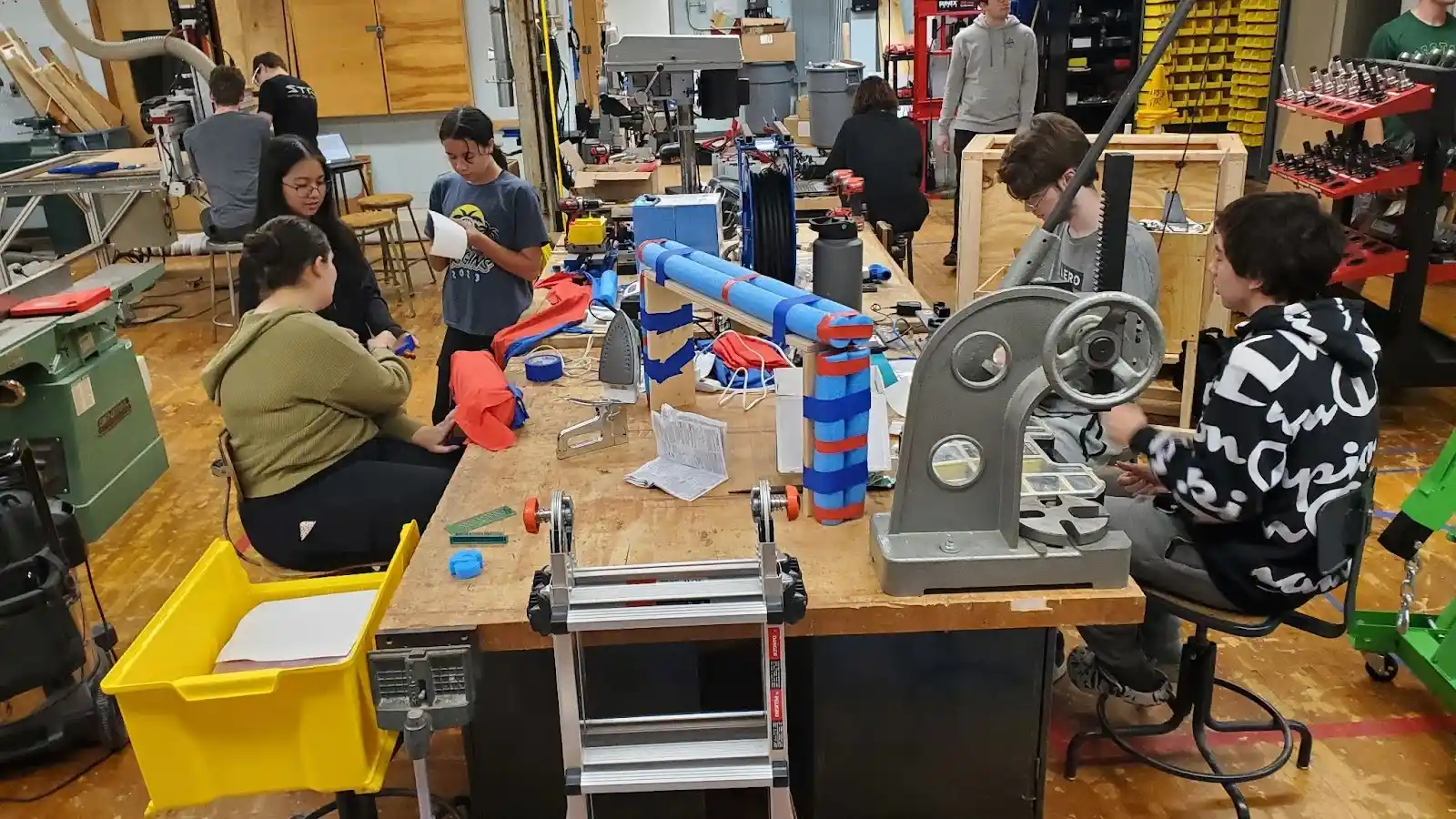
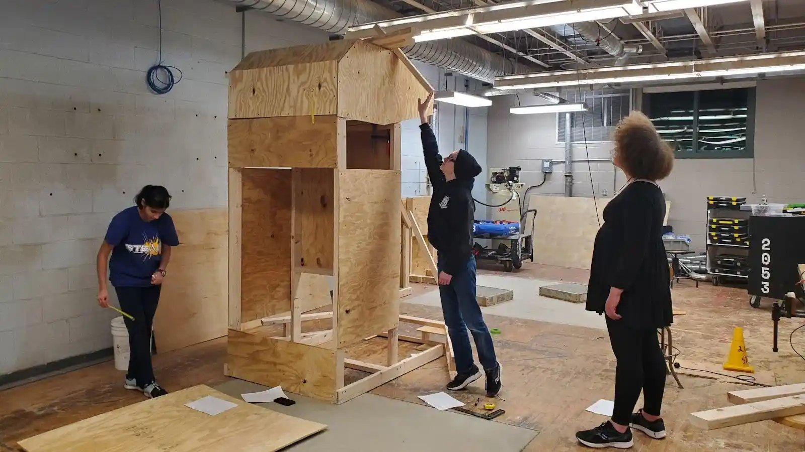
In addition to building Bruin we also had to build the field elements which are the targets used for scoring. Here we are building the field element called the Speaker used to test the performance of the robot’s shooter. The specification for the Speaker is provided in the package of documentation for the competition.
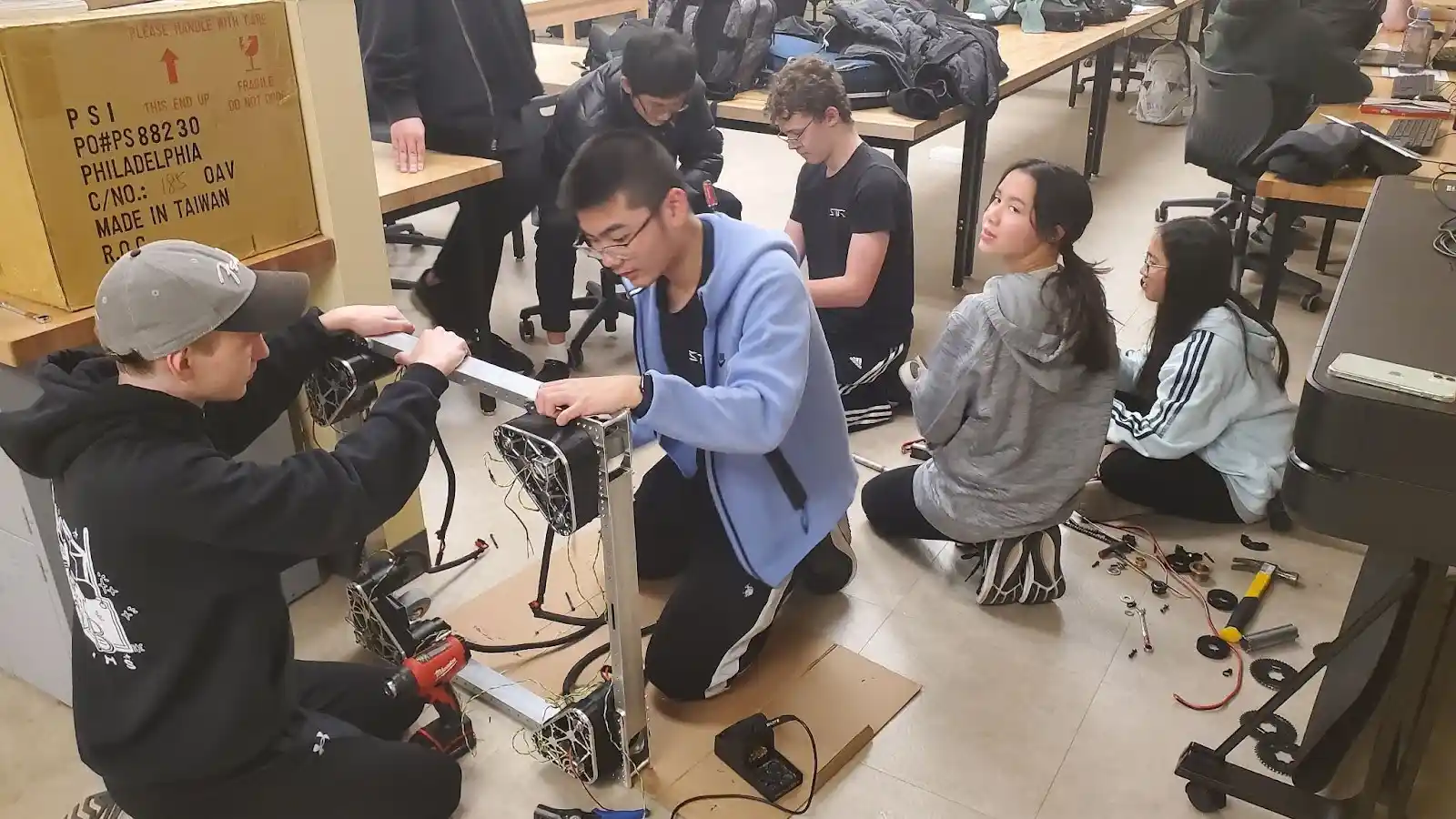
The robot build is divided into several major components. The base of the robot contains the battery, drive motors for the wheels, and a majority of the electronics. Team members are starting the assembly of the base of the robot.
The frame that houses the battery, electronics, motors, and wheels must be strong to survive the banging and crashing during the competition matches.
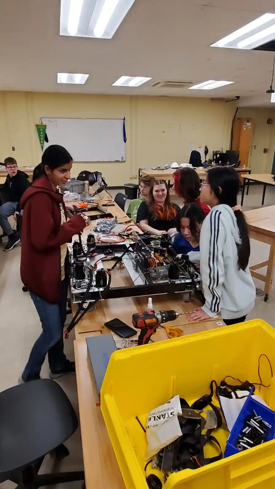
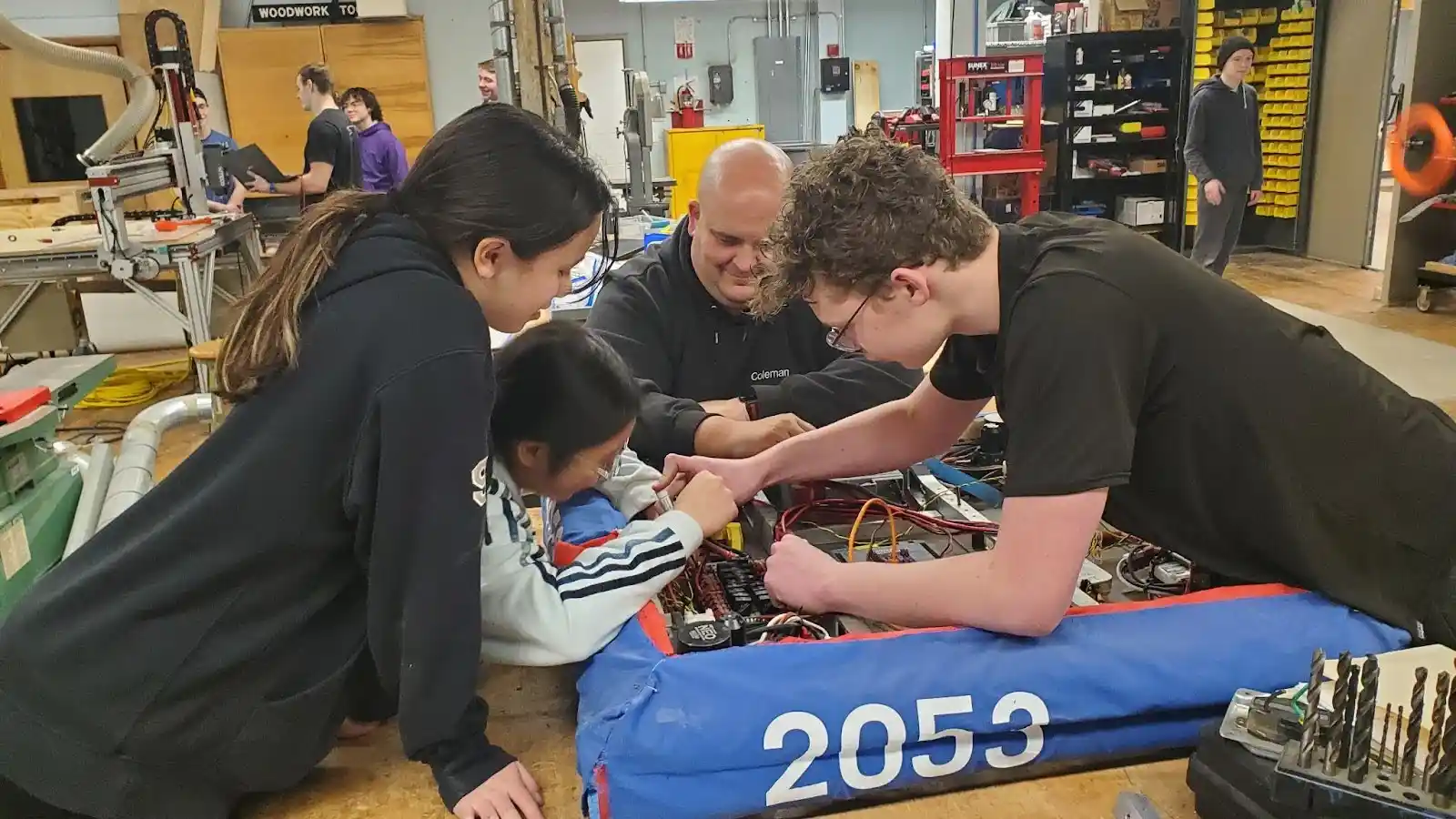
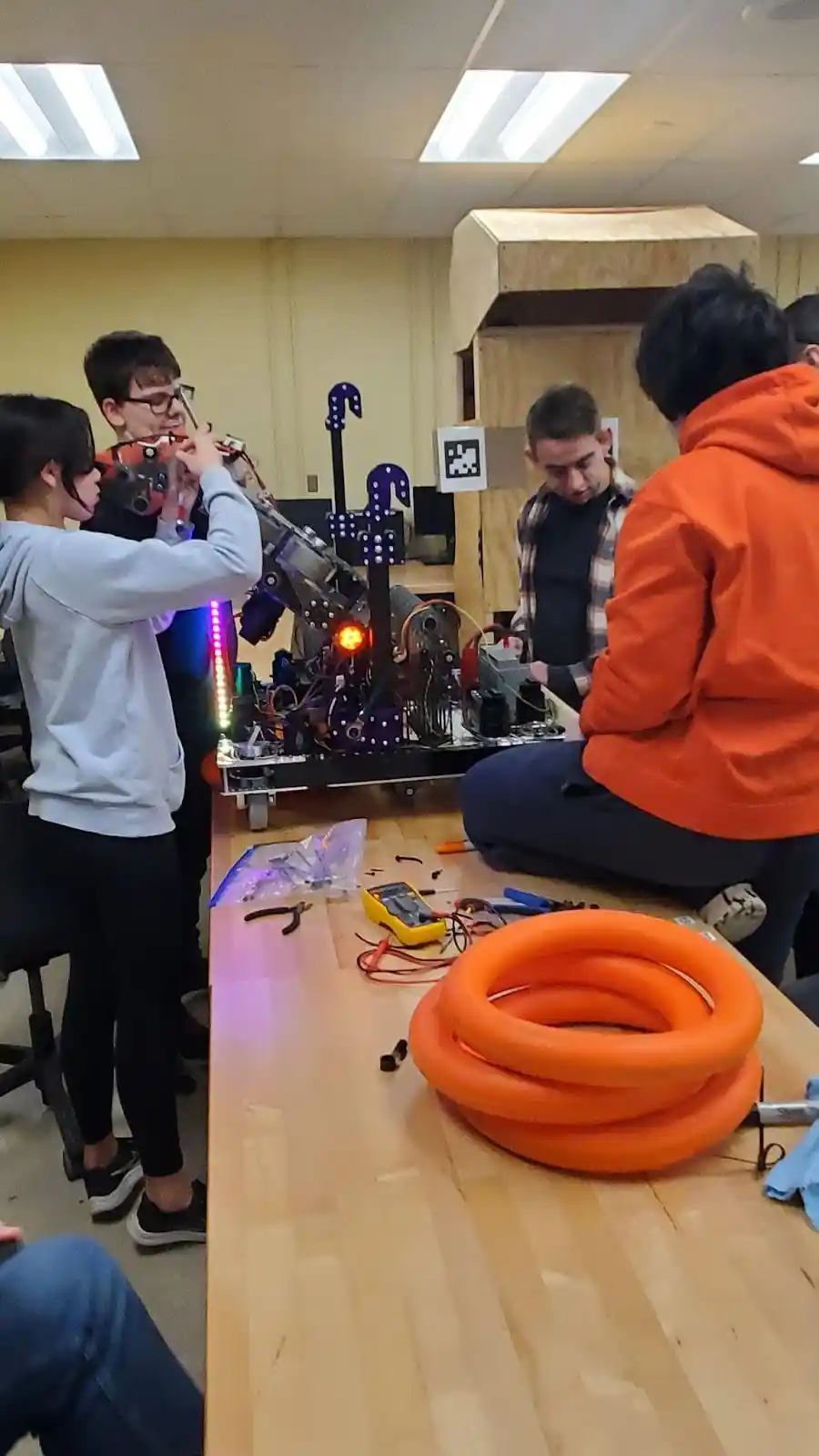
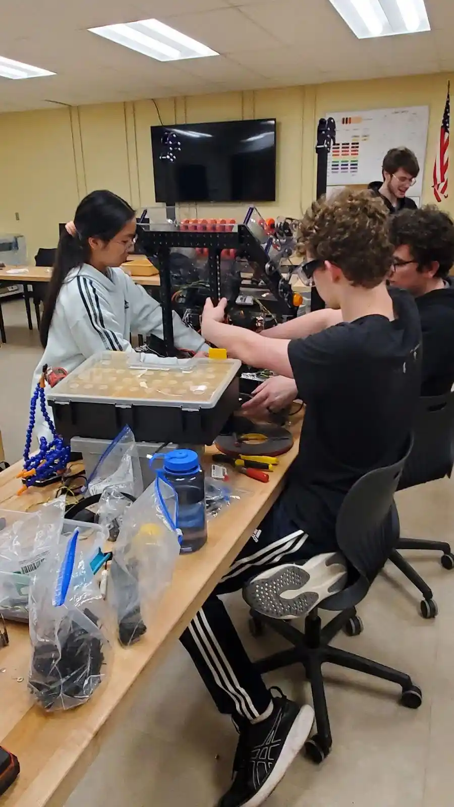
The Team is wiring up the electronics, motors, and batteries housed within the frame. All the components and wiring within the base must be strongly secured to withstand the banging and crashing in a match. The robots can weigh up to 125 lbs and can travel approximately 19 ft/sec (13 mph). During a match there are six robots whizzing round the field scooping up rings and shooting at the targets to score points. The robots inevitably run into each other.
The development of the Shooter that shoots rings into the Speaker started with developing a prototype and testing the performance by shooting into the Speaker field element. Adjustments on the prototype shooter includes spacings of the motor mechanisms,angle of the shooter, and speed of the wheels that propel the ring into the Speaker.
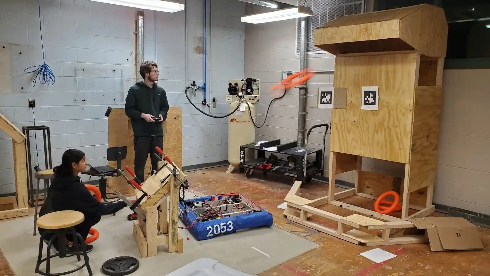
The Team is determining how to position the Dunker on Bruin so that the ring is guided into the Amp opening.
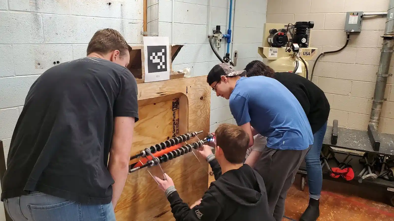
The Team developed and tested the prototype for the ring Intake. Rings are laying on the floor. The Intake is underneath Bruin’s chassis. Bruin maneuvers to capture and guide the ring up into the Shooter.
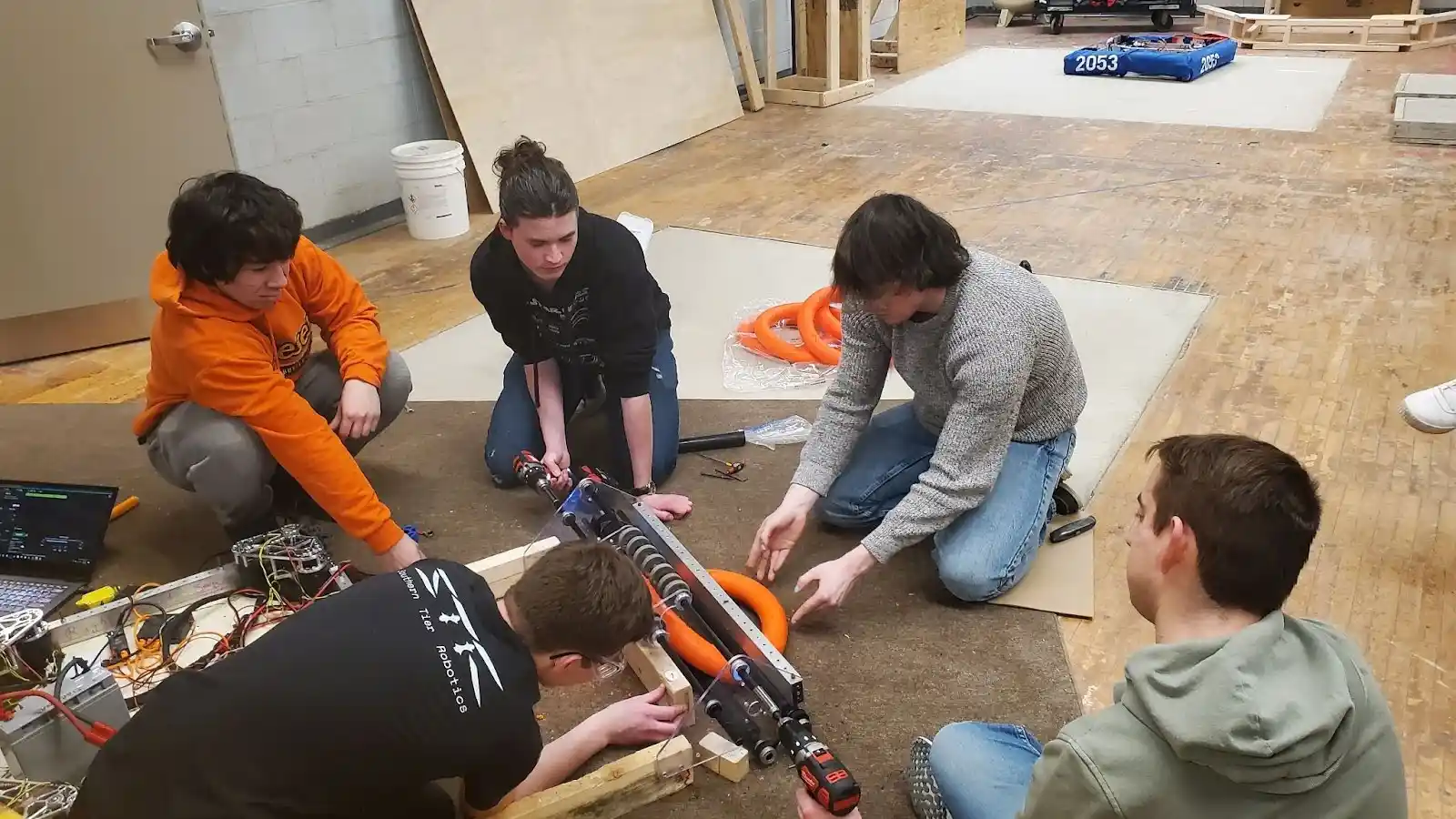
The Team is assembling Bruin in the classroom portion of the shop. In the front of the picture the Team is doing the initial assembly of the shooter based on the prototype. In the back is the Speaker target that will be used during Bruin testing.
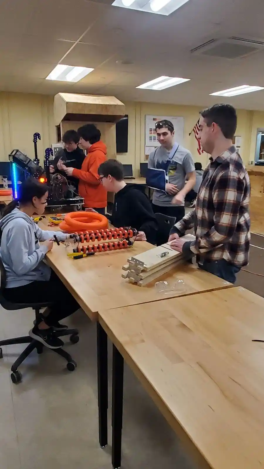
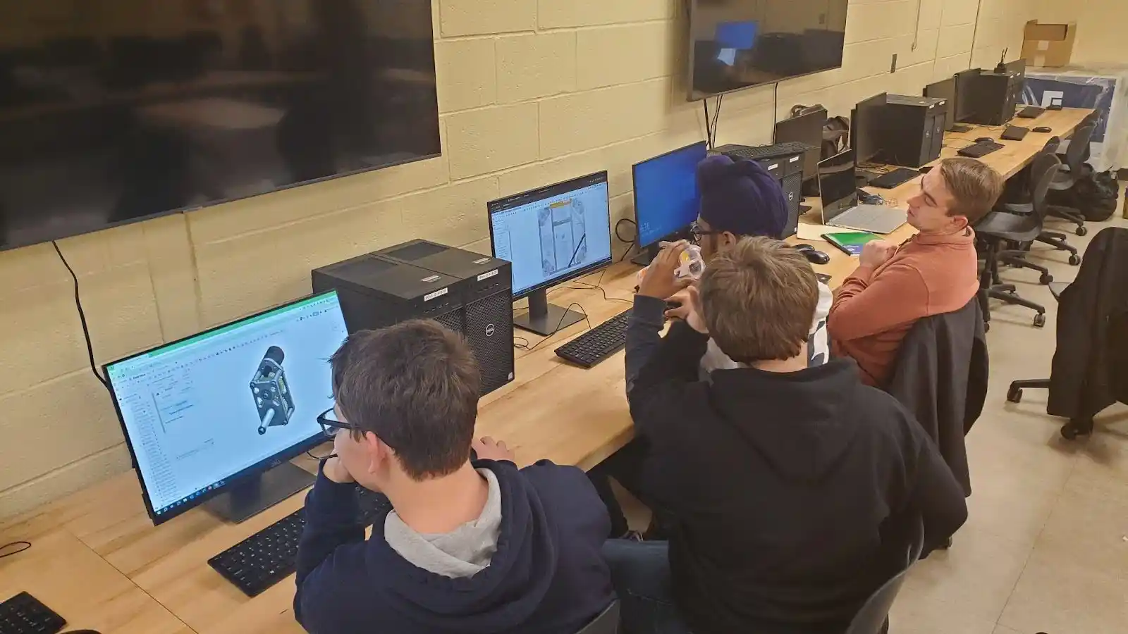
Throughout the build and test phase there were inevitable changes to correct mistakes and improve performance. The CAD team had to update and refine the design quickly so new parts could be manufactured and installed.
Bruin is coming together nicely!
Software is the glue that ties all of electronics and hardware together. Regular gaming controls are used to control the various capabilities of the robot including speed and direction control, ring Intake, controlling the Shooter and Dunker, and providing information to the Driver and Operator about the state of Bruin in the match.
The Team is mulling over the software to be developed and what the forward plan is.
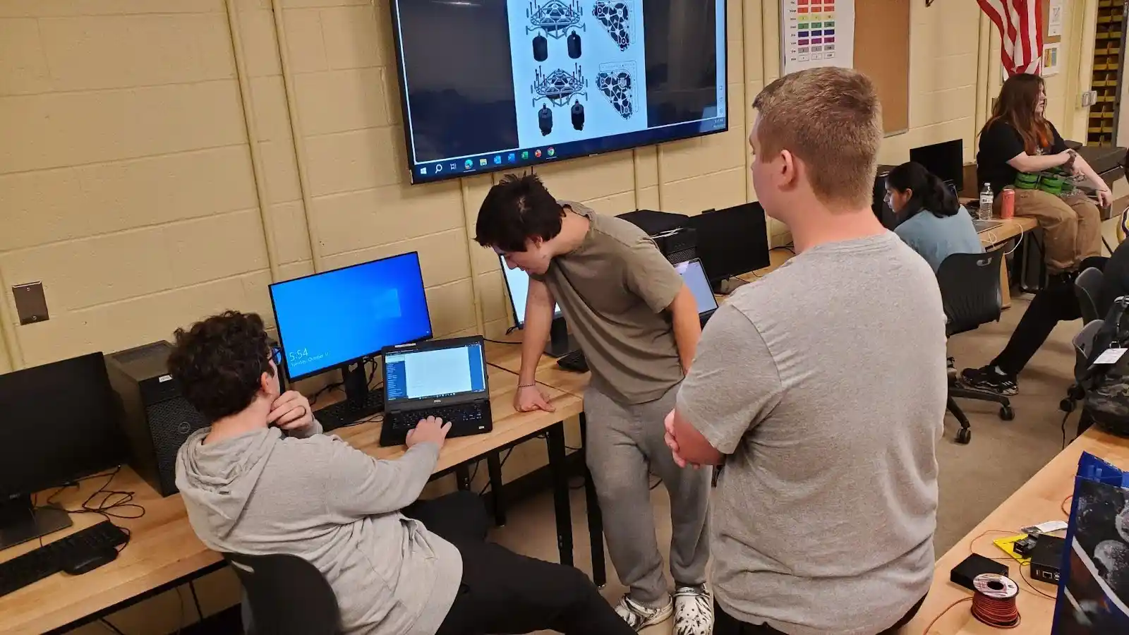
Multiple laptops are needed to develop and test the software. One laptop is used to develop the software and the other laptop is used during operation of Bruin with the game controllers.
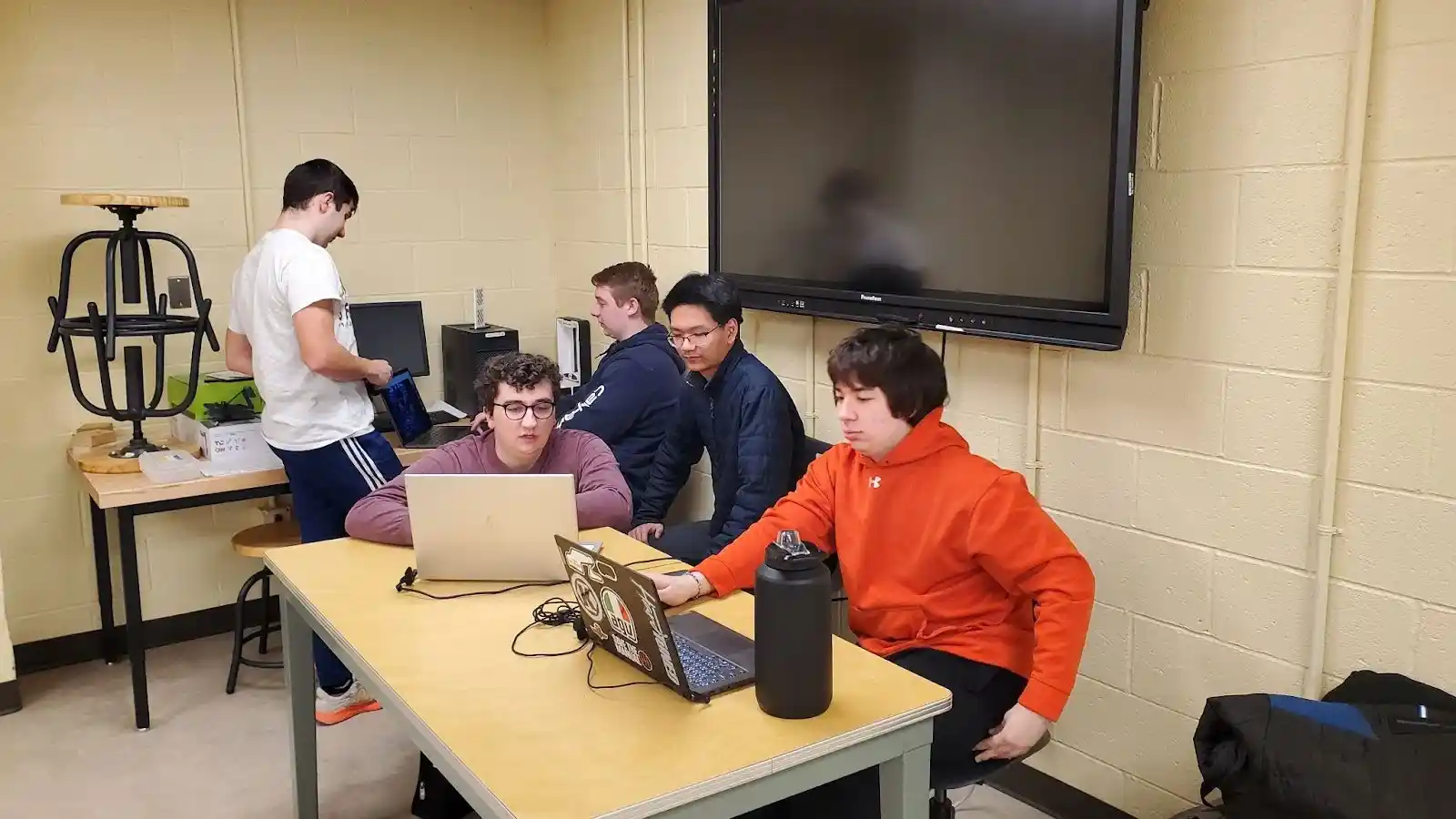
Testing the drive speed and direction software.
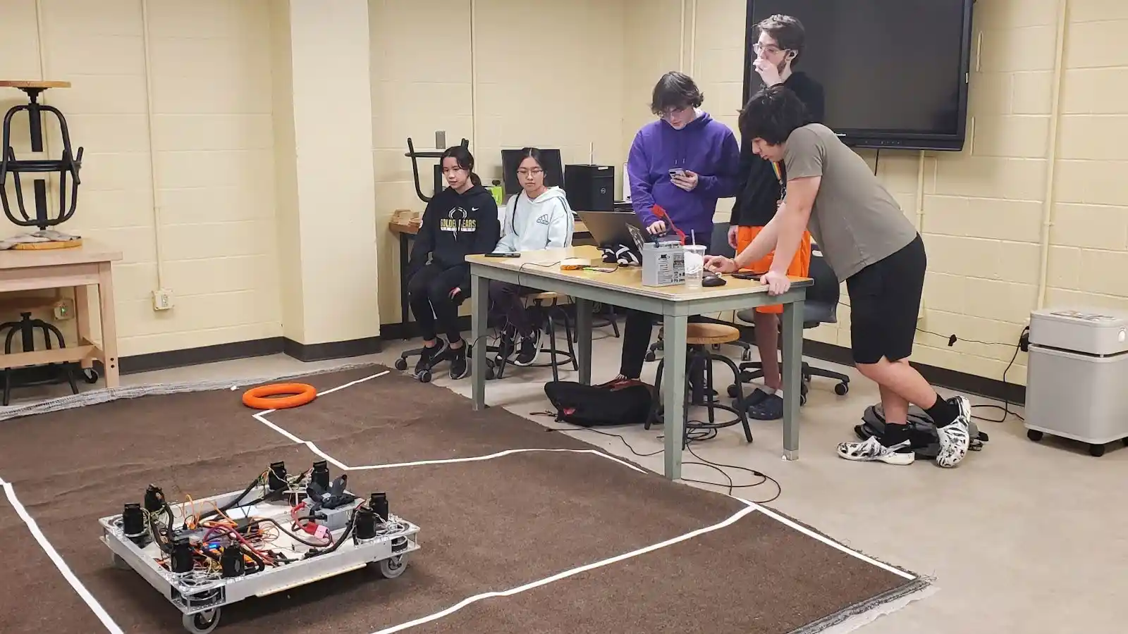
Bruin is complete and ready for testing!
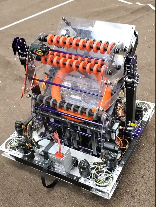
Here is a CAD representation of Bruin with the major components identified. The “Intake” picks up the rings that are on the floor and feeds it into the “Shooter”. The Shooter fires the rings into the Speaker which scores points. The “Dunker” is used when scoring points in the “Amp”. The “Climber” is used at the end of the match. The Climber extends upwards to latch onto a chain and then hauls itself up so that it is completely off the ground gaining additional points. The “Drivebase” houses all the computer and electrical components and motors for the wheels. Surrounding the Drivebase will be bumpers that protect the Drivebase from running into other robots.
This video is a CAD render of Bruin providing a 360 degree view.
”Bruin Render”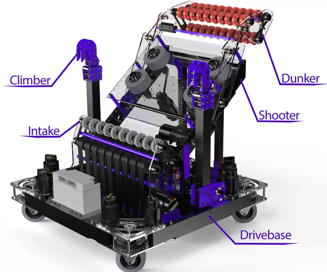
With the initial build of Bruin the Team proceeds to testing the complete robot. Here the Team is testing the ability of the Shooter to shoot rings into the Speaker.
”Auto Test”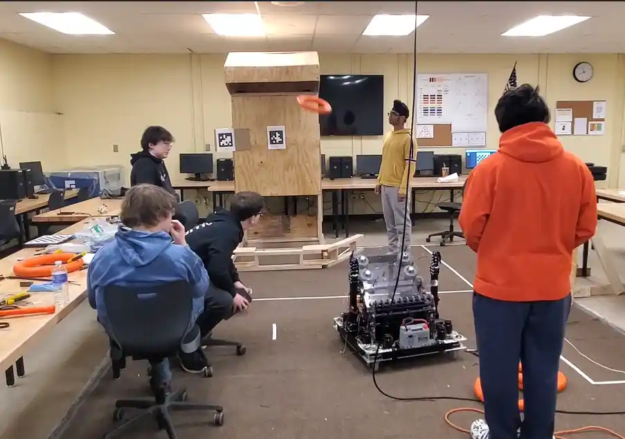
Another way to score points is for the Dunker to place a ring in the Amp. When a ring is obtained through the Intake it goes into the Shooter. You can see the intake of the ring at the beginning of the video. The Dunker moves in front of the Shooter so that the ring is directed downwards into the Amp instead of shooting up into the Speaker.
”Dunker Test”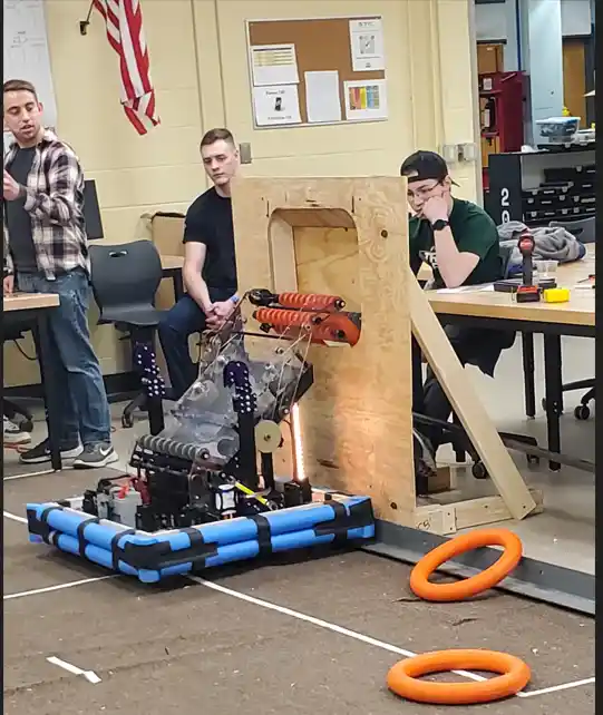
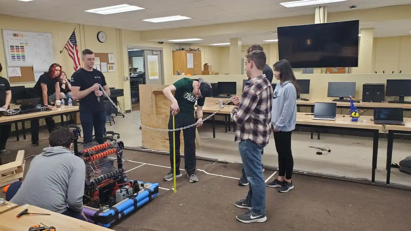
We’re doing a test of the Climber. Bruin will be driven under the chain and extend the Climber arms up and latch onto the chain. Then the arms will ratch down which pulls Bruin up and off the ground.
During a match there will be six robots on the field. There are two teams of 3 robots facing each other so the Bruin driver will have to contend with the opposing team trying to interfere with Bruin scoring.
”Full Robot Test”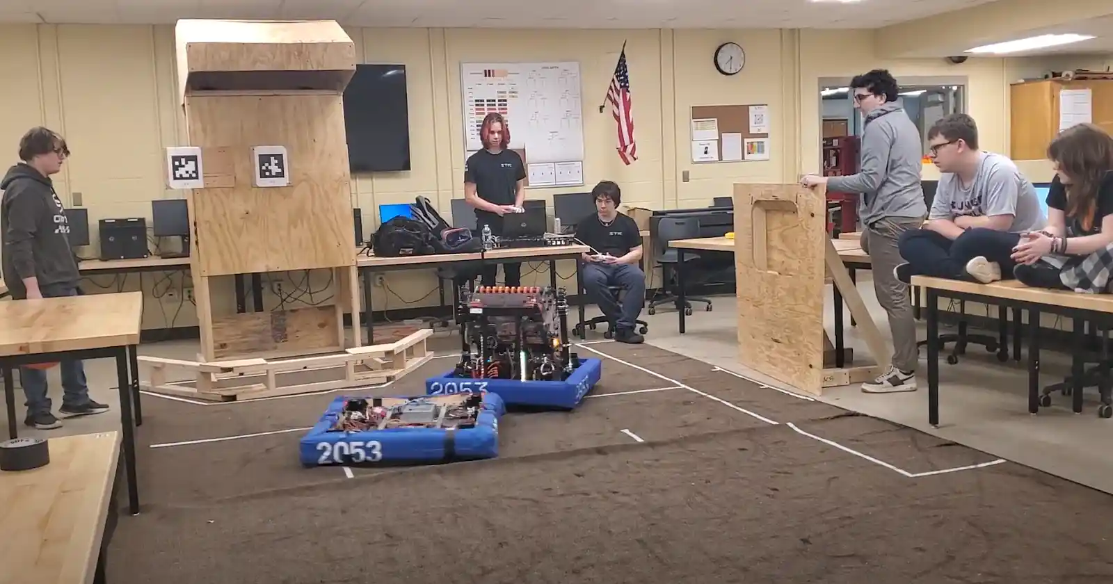
In the next blog we’ll see what it’s like at the Pittsburgh and Albany regions competitions.
